Loading...
Please wait while we prepare your content
Picture opening a spreadsheet nobody labeled: columns with mystery headers, duplicate rows, and no obvious way to tell which sheet “owns” which fact. Relational design starts earlier—with a shared map everyone can argue with using the same vocabulary.
An Entity Relationship (ER) diagram is that map. It shows what you store (entities), what you record about each thing (attributes), and how things connect (relationships). Teams use ER diagrams to align on structure, catch mistakes cheaply, and document the system long after the first developer moves on. You will also see them called ERDs or ER models; they borrow a grammar-like habit—entities as nouns, relationships as verbs.

Why bother?
CREATE TABLE commits you to awkward fixes.A definable thing you care to store data about: a person, object, concept, or event. Treat entities as nouns—Customer, Student, Product, Shipment. On a diagram they usually appear as rectangles.
Attributes are the facts you store about an entity: names, dates, counts, codes. They answer “what do we know about each instance?”
Types of attributes:
A relationship is how entities link or act on each other—enrolls in, places, assigned_to. Read it as a verb between two nouns: Student enrolls in Course. Visually you may see a diamond (Chen style) or a labeled line (common in Crow’s Foot tooling).
Several styles exist; each trades readability for tradition in a given tool or textbook.
| Notation style | What you will notice |
|---|---|
| Chen | Rectangles, diamonds, ovals—classic academic |
| Crow’s Foot (IE) | Line endings show cardinality at a glance |
| UML | Class-diagram look from object-oriented UML |
| Barker’s | Common in some Oracle-oriented methods |
This lesson focuses on Crow’s Foot (Information Engineering) notation because it appears everywhere in industry tools and job-facing schema sketches.
The crow’s foot is the forked symbol that means “many.” Together with a straight bar (one) and a small circle (zero, optional), you can read maximum counts and whether a link is required without decoding a separate legend every time.
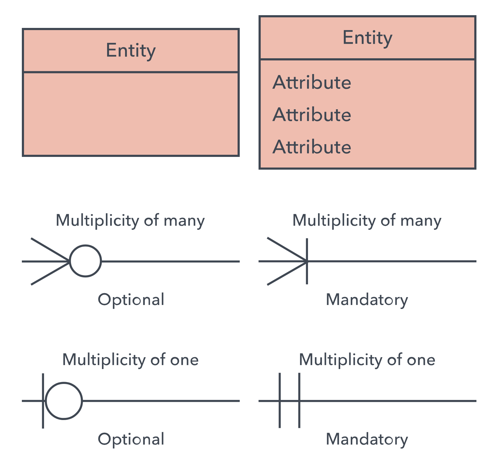
| Symbol | Meaning | Plain language |
|---|---|---|
| (single bar) | One | Exactly one |
| ○ (circle) | Zero | Optional on this side |
< or crow’s foot | Many | Zero/one-or-more set |
Cardinality — At most, how many partners can this side have: one or many?
Optionality — Must the link exist? Mandatory reads as a bar (|); optional reads as a circle (○).
Frequent combinations:
| Ends (simplified) | Meaning | Read as |
|---|---|---|
|─| | One to one | Exactly one each way |
○─| | Zero or one | At most one (optional) |
|─< | One to many | At least one on the “many” side (mandatory from the “one” side) |
○─< | Zero to many | Any number including none |
Each row on side A pairs with exactly one row on side B, and vice versa.
Example: One person, one passport number record you treat as a separate entity.
┌──────────┐          ┌──────────┐
│  Person  │──|────|──│ Passport │
└──────────┘          └──────────┘
More examples: employee ↔ parking permit; user ↔ profile row (when split for security or size).
One parent can have many children; each child points back to one parent.
Example: One customer, many orders—each order belongs to one customer.
┌──────────┐          ┌──────────┐
│ Customer │──|────<──│  Order   │
└──────────┘          └──────────┘
More examples: department → employees; author → books (single-author model).
Rows on both sides can link to multiple partners—classic enrollments, tags, team membership.
Example: Students take many courses; each course has many students.
┌──────────┐          ┌──────────┐
│ Student  │──<────>──│  Course  │
└──────────┘          └──────────┘
Reality check for SQL: You do not implement M:N as two foreign keys on one table in the obvious way. You introduce a junction (bridge / associative) entity so the database only has 1:N edges.
Conceptual sketch:
Student ──<────>── CoursePhysical pattern: two foreign keys in the middle.
┌──────────┐          ┌────────────┐          ┌──────────┐
│ Student  │──|────<──│ Enrollment │──>────|──│  Course  │
└──────────┘          └────────────┘          └──────────┘
The junction (Enrollment) usually holds Student_ID, Course_ID, and facts about the pairing (enrolled_on, grade).
Use a simple template:
“[Entity A] [verb] [cardinality phrase] [Entity B].”
Then flip the sentence and read toward Entity A.
Customer–Order (crow’s-foot pattern |──< from Customer toward Order):
Student–Course (optional-many both ways, often drawn >──<):
If both readings sound wrong for the business rule, the diagram—not the database—needs fixing.
Crow’s Foot diagrams are the sketchpad for relational design: entities in boxes, attributes as fields, lines carrying cardinality and optionality. When you open the next lessons, you will translate these shapes into keys, tables, and constraints—and the diagram will still be the fastest way to explain your schema to another human.